Applications
• PCB Characteristic Impedance Measurements
• Oscilloscope and probe response testing
• Cable and interconnect response testing
• Cable Length Measurements
Specifications
|
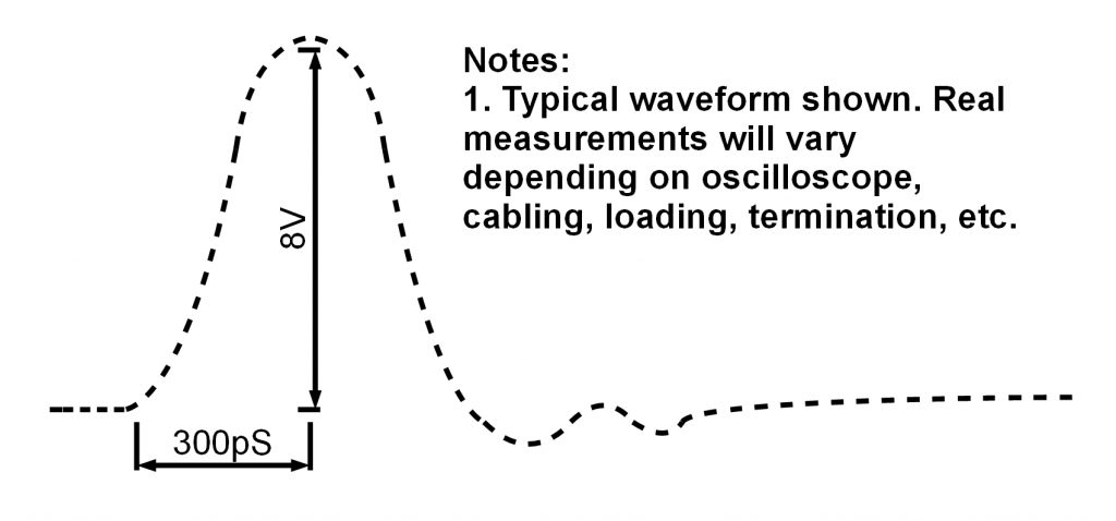
Rise Time |
300pS, Note 1 |
|
Amplitude |
8V, Note 1 |
|
Connector |
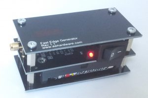
SMA female |
|
Power Source |
Two AA batteries, Alkaline or NIMH |
|
Power Consumption |
Less than 10mA when powered with 2 Alkaline cells |
|
Dimensions/Weight |
9cm x 5cm x 5cm, 120g(including batteries) |
|
Notes: 1. Real measurements will vary depending on oscilloscope, probes, cabling, termination, etc. |
|
Typical Pulse Shape

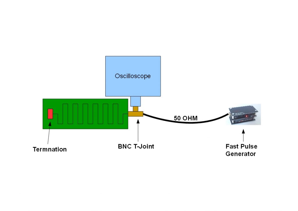
Appnote 1 : Measuring PCB Impedance

Instructions
1. Connect Edge generator to PCB using a 50 ohm cable.
2. Connect oscilloscope to the point where the 50 ohm cable connects to the PCB.
3. Turn on the pulse generator and compare incident waveform to the reflected waveform. Adjust
termination until the reflection is under control.
Notes
1. BNC T-Joint can be omitted if signal can be probed directly on the PCB.
2. Depending on physical obstructions, 50 OHM cable can be omitted and pulse generator can be
connected directly to PCB.
3. Adding test traces to the break away tooling strips around the edge of a PCB panel is a convenient
way to verify impedance.
4. A potentiometer can be handy to quickly adjust termination, instead of having to solder/desolder
discrete parts. Just keep in mind that it has higher pin inductance compared to a surface mount
resistor.